Updated:2025-03-13
Views:2594
 WeChat
 QQ
QQ
 Online Service
With this preamp, sub-microvolt signals can be displayed on scopes which typically only go down to 1mV/div on the vertical axis. The preamp includes an analog true differential input and an analog low-pass filter (tunable 1Hz-1MHz). Input-referenced RMS noise spectrum for f >100Hz is 4 nV/√Hz or less, so for example, even with 1000 x gain, total noise from 100 Hz to 1000 Hz is less than 1 div peak-to-peak on a 1mV/div vertical scope setting (assuming a low-impedance input). Most oscilloscopes are designed to display high-frequency (fast) events that may intrinsically have noise of a millivolt or more. However, low-frequency signals have much less intrinsic noise, so a low-noise preamp and a bandwidth-limiting filter are essential for small signals at low frequency.* Most amplifiers have a white noise spectrum (a flat spectral curve) at all frequencies above ~1000 Hz. This white noise spectrum is usually specified as a certain number of nV per √Hz. However, unlike typical passive resistors, the equivalent input noise spectrum of solid-state amplifiers (in nV/√Hz) becomes higher at low frequencies. Typically the number of nV/√Hz is proportional to ~1/f for f ≤10Hz. The table below shows actual noise of the LNA 10 in various frequency ranges. At all frequencies, the LNA 10 has much less noise than typical solid-state amplifiers.


The intrinsic “white” noise of a resistive electrical circuit at room temperature is proportional to √(R∙Δf), which is the square root of the product of source resistance multiplied by the bandwidth being investigated. For low source resistance and low frequencies, noise is low. For example, a 1000 Ω resistor will have an intrinsic RMS noise of 13 nV in a Δf =10 Hz bandwidth, with 10 Hz being the bandwidth, for example, associated with the frequency range 0-10 Hz, or with the frequency range 102 Hz-112 Hz. The noise will become twice as much if the bandwidth being studied is 4 times as wide (i.e., 40 Hz), or if the resistance is multiplied by 4.

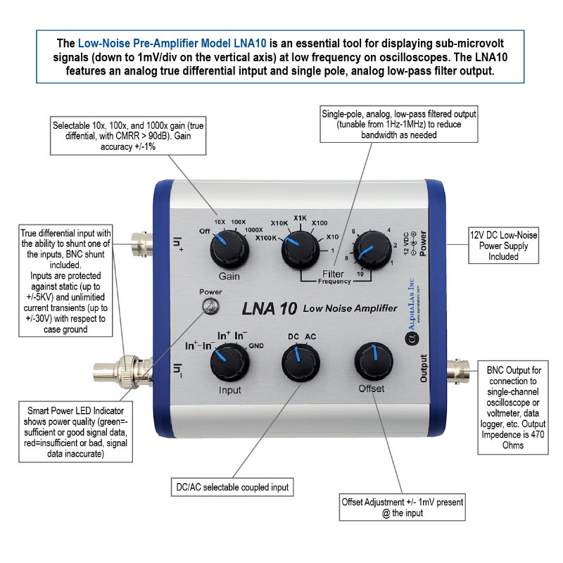
Output has a single pole lowpass filter, tunable from 1 Hz to 1 MHz. This feature reduces the bandwidth, as needed.
Selectable DC/AC coupled input (“AC” passes through a .3Hz highpass filter, 1 pole): On DC, each input must be between -0.4V and +0.4V, with respect to case ground, for accurate readings. When set to AC, a DC offset up to +/- 30V can be present. (However, if the inputs rapidly vary by more than .8V peak-to-peak, then the slew rate must be ≤ 2V/sec for accurate amplification.)
Inputs are protected to +/- 5KV static and +/-30V unlimited current transients, with respect to case ground.
Output impedance is 470 Ω.
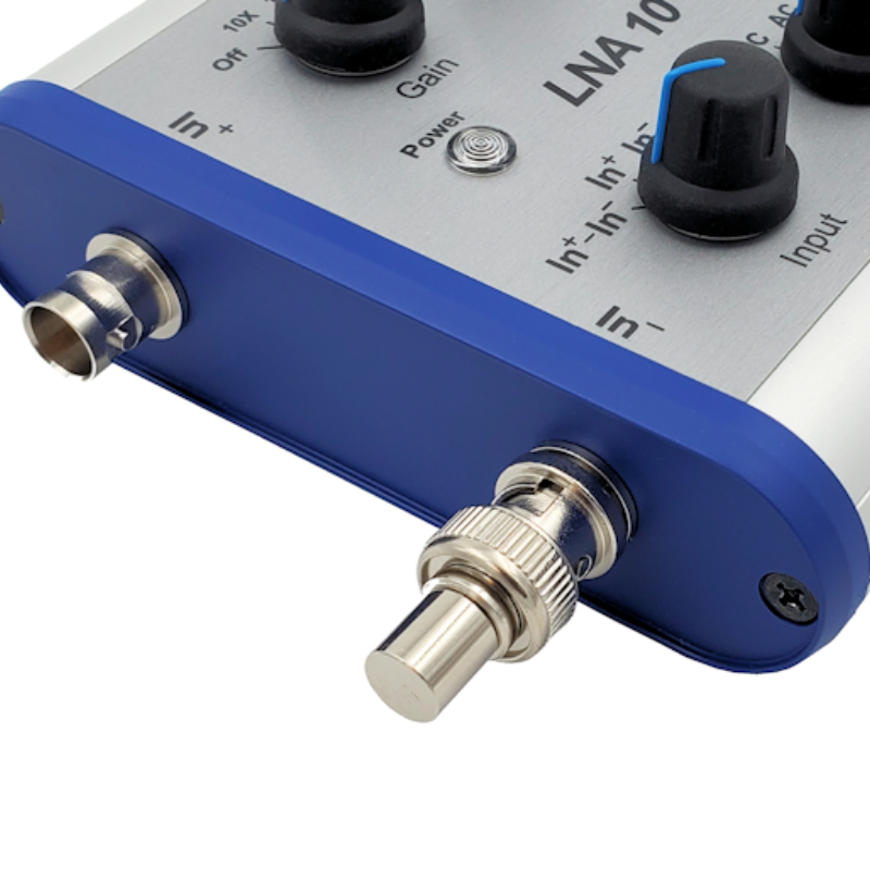
Selectable gains are 10x, 100x, 1000x (true differential, with CMRR > 90dB). Also positive and negative single-ended inputs can be selected, as well as reference ground. Gain accuracy: +/-1%. (The LNA 10 does not include a 1x gain.)
An offset adjustment, equivalent to +/- 1 mV at the input, is present.
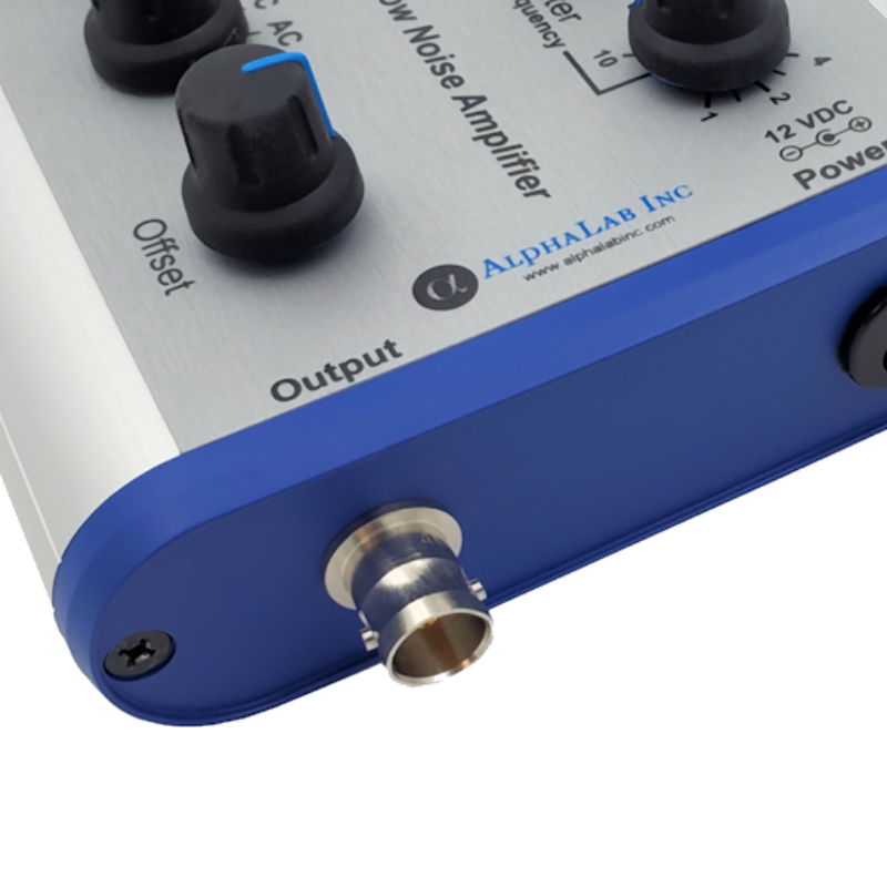
A BNC output (100 Ω) is intended to be connected to a single oscilloscope channel, or to another voltage-reading device (data logger, voltmeter, etc).
| applications: | Electrical Engineering, Scientific Research |
| category: | Voltage Measurement |
Customer Service QQ
Customer Hotline:
Technical Supports