
Instrument Expert
Original factory packaging

Service Hotline:
(+86)010-52867771
Instrument Expert
Original factory packaging
Service Hotline:
(+86)010-52867771
Updated:2025-03-13
Views:2572
 WeChat
 QQ
QQ
 Online Service
 Datasheet
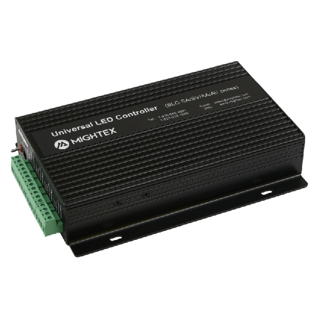
Mightex has developed a series of computer-controllable, multi-channel, universal LED drivers, which can be used to drive any type of LED in any of the three (3) modes: ‘NORMAL’ (or ‘constant current’), ‘STROBE’, and/or external ‘TRIGGER’ mode. Each unit comes with PC-based software with a user-friendly GUI, which enables users to drive LEDs without the need to write any code. In addition, a powerful SDK is provided, in order for users to write their own software and to integrate Mightex’s LED drivers into their own systems. Furthermore, the drivers have a built-in security feature, allowing users to limit LED driving current and voltage.
This datasheet covers four (4) product series (i.e. FA, FV, XA and XV series) of High-Precision Universal 4-Channel LED Controllers with External Triggers and 0.1mA Current Resolution, which currently includes 4 models in total. All FA/FV/XA/XV LED controllers have 0.1mA current resolution, and a maximum current of 100mA in DC mode and 350mA in pulse mode.
Features:
Driving current up to 100mA in DC mode and up to 350mA in pulse mode, with over current protection
Current resolution 0.1mA
Computer controllable
USB and RS232 interfaces
Universal – suitable for any LED
Capable of driving variable loads
User friendly application software with GUI
SDK and Rich RS232 command set included for custom applications
Normal, Strobe and Trigger mode for every channel
Programmable constant current, pulse-width modulation and/or arbitrary waveform
Up to 23.5V output voltage for each channel Programmable rising or falling edge external trigger
Built-in non-volatile memory, can be used without a PC
Applications:
Machine vision
Displays
Microscopy
Semiconductor equipment
Testing instruments
Medical instruments
Lighting
| Parameters | SLC-XAxx-xx | SLC-XVxx-xx | SLC-FAxx-xx | SLC-FVxx-xx | Unit |
| Power Supply Input Voltage, Vdc | 9 ~ 24 | V | |||
| Power Supply Input Current | < 4,000 | mA | |||
| Per Channel Driving Voltage (max) 1 | (Vdc - 0.5) | V | |||
| Per Channel Driving Current | 0 ~ 100 (“NORMAL” MODE) | mA | |||
| 0 ~ 350 (“STROBE” or “TRIGGER” MODE) | mA | ||||
| Output Current Resolution | 0.1 | mA | |||
| Output Current Linearity | +/-0.4 (or +/-0.5%) | mA | |||
| Output Current Repeatability | +/-0.1 (or +/-0.2%) | mA | |||
| Trigger Input High Level | 4.5 ~ 10.0 | V | |||
| Trigger Input Low Level | 0.8 (Max.) | V | |||
| Forward Voltage Monitoring Accuracy | N.A. | +/-10 | N.A. | +/-10 | mV |
Notes: 1. Maximum Output Voltage is 0.5V less than the Power Supply Input Voltage. For instance, with a Power Supply Input Voltage of Vdc = 24V, the Maximum Output Voltage Vmax would be Vdc – 0.5V = 23.5V.
2. Each output channel can be individually configured to work in one of the following three (3) modes, controlled through a PC-based software with GUI. In all three modes, overdrive current limit can be set:
Normal: Constant current output at any value from 0mA to 100mA with 12-bit resolution.
Trigger: External trigger signal could be used to turn on each individual channel, generating driving current with any user-defined waveform. Alternatively, each output channel can work under the “FOLLOWER” mode, in which the current output follows the waveform of the trigger input; and
Strobe: Internal Strobe Generator generates frequencies as high as 25KHz. The strobe signal (i.e. current levels, duty cycle and strobe frequency) can be set through software. For AA and AV series, the strobe signal can be a user-defined arbitrary waveform with 128 data points.
3. Arbitrary Waveform. Using the included application software or SDK or RS232 command set, users may define any arbitrary waveform using 128 data points.
| Parameters | SLC-XAxx-x | SLC-XVxx-x | SLC-FAxx-x | SLC-FVxx-x | Unit |
| Timing Resolution | 20 | μs | |||
| # of Data Points for Waveform Definition | 128 | 2 | |||
| Trigger Pulse Width | 100 (Minimum) | μs | |||
| Max Trigger Delay | 25 | μs | |||
Customer Service QQ
Customer Hotline:
Technical Supports


 3003988120
 yiqi.com
 bio-equip.com
 b2bwork.baidu.com
 baidu.com